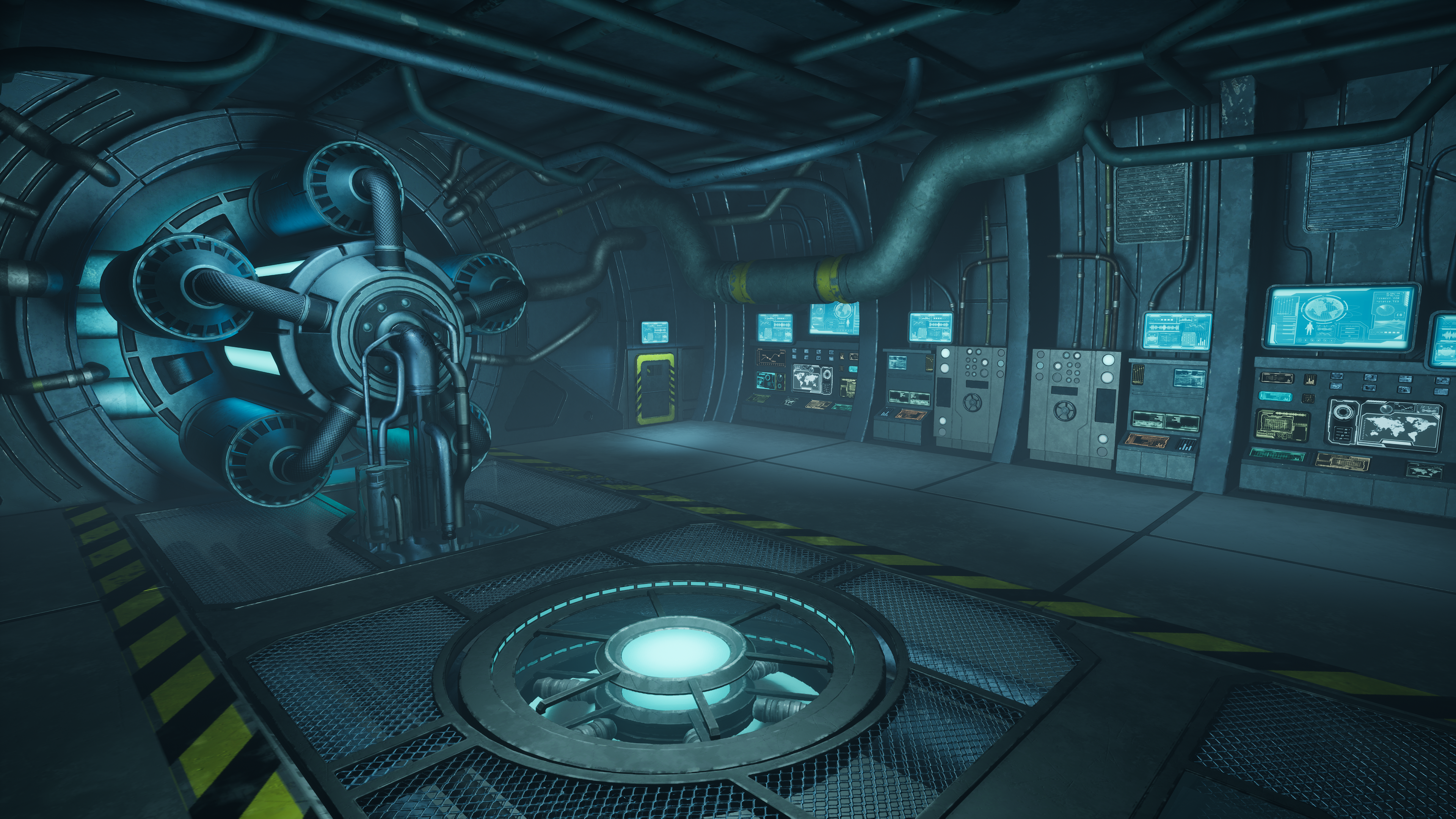
These were my references. My primary reference were, of course, my portfolio pieces, as shown below. As you can see, the screens in both the images seem very different, but in fact, involve the same process of creation.
 |
| The Airlock |
 |
The Airlock
DIFFERENCE |
 |
| DESIGNER VS PAINTER |
As most of us are familiar with Substance Painter, I thought I'd give a quick introduction into Designer from that perspective. Designer is what you'd call a 'material authoring' software, that is, it allows you to procedurally generate your own materials and textures. It is node-based, allowing you to connect various nodes together to generate various shapes and textures. The materials that result are particularly useful when they're tileable, which can be used to apply on various meshes.
I once heard someone describing the difference between Painter and Designer with a very simple metaphor. Designer is where you create the paint needed to paint, say, a wall, and Painter is where you apply that paint to specific areas of the wall.
NODES
Nodes are the building blocks of any material you make in SD. They are basically operators that transform any input in a very specific way. Like in the below example, where a bitmap (explained in greater detail below, but for now just consider it as an imported image) is being transformed in 2 dimensions (X and Y) but in a very specific way (it's being turned upside down).
 |
| NODES |
 |
| START WITH HEIGHT! |
When working on creating any material, almost always start with Height, because it will flow into every other aspect of material, and once you're done with height, about 80 percent of the work is pretty much done. Also, always start with the macrostructure, then go into details, which is true for any texturing software.
LINKS
There can be one of two types of links found in every node. Yellow links and grey links.
|
| YELLOW LINKS |
Yellow links are for color nodes, like the base color texture. It doesn't always work out like that, but that's a good way to explain it simply.
 |
| GREY LINKS |
Grey links are for - you guessed it! - greyscale connections like the height textures.
You can't join a yellow output to a grey input, because it will create an error and refuse to show an output. Errors are easily observable with the presence of a red line and a big gaping black hole in the output node. I will show you later how to convert color to greyscale. The inverse is also possible.
A useful shortcut to remember is that double clicking any node will display it in Output - 2D View. This is demonstrated below, as I've double clicked the Edge Detect Node (see the white outline highlighting the selection?) and it displays immediately in the adjacent 2D View.
 |
| DOUBLE-CLICK FOR 2D OUTPUT |
 |
FINAL RENDER - UI SCREEN
PROCESS
Now, I'll show you how I made the below HUD as a sample. It's part of a tutorial by 3dEx, aYoutube channel that showcases some amazing textures and materials created in SD. I followed the tutorial in order to learn SD in such a way that was immediately applicable to what I was doing with this research project.
In order to demonstrate what I have learned, I will share my workflow. I will focus a lot on individual nodes (after all, this is a tutorial for dummies!), but occasionally show how I pulled off something a little more complex.

SHAPE NODE
You start off, of course, with a shape node. As the name suggests, it can generate any of the basic shapes like squares, circles and a few other complex ones. These have parameters with which you can scale it in any direction. Here, I started with a square which I then scaled into a rectangle. This will form the basics of my screen. |
|
EDGE DETECT
Edge Detect Node, as can be inferred, isolates the edge of a shape or any input.
Edge Detect Node is a favorite of mine, because it works both in creating masks, as well as in the later stages of material creation, where you have to create effects such as edge wear for metals, for example. For the latter this node will help isolate the borders of a shape, which can then be blended with various grunge options present by default in SD. |
|
|
 |
| BLEND |
In the above screenshot, you can see the node 'Blend' in action. It acts quite like the blending modes in Substance Painter and Photoshop. Here, it's multiplying a simple Shape node displaying a rectangle, with an Edge Detect Node to create a much more rounded rectangle, which is not a shape you can get by default.
The Transformation 2D is a pretty self-explanatory node. It allows you to translate, rotate and scale inputs in any way or form. Very valuable for this sort of project.
Bitmaps are nodes that are dependent on external resources that are not found by default in SD. For example, in this particular case, I have imported a sci fi panel outline of sorts to use within my screens. Images can be either imported or linked, the latter being particularly useful when you plan on updating the image later and just need a 'proxy' of sorts within the graph for visualization purposes.
Bitmaps are a bit annoying sometimes because they will always recognize any image as being a color bitmap, even if the image itself is only a greyscale. This will cause problems as demonstrated below, when I tried to plugin the bitmap into a gradient map, which should provide me with colors, but instead gives only a red connecting line, indicating an error.
There is a specific node, Greyscale Conversion, that converts color to greyscale, which I had to use quite a lot for this project.
Gradient Map, as the name suggests, isn't just for providing one color, but actually allows you to mess around with an entire gradient. In my scenario, I just needed the one color, so I stuck with it.
The Blend Node in action again. Here it's demonstrating the immensely useful function of 'Add'.
|
| INVERT GREYSCALE |
Invert Greyscale and Levels are self-explanatory, as they're available in other software such as Photoshop and Substance Painter.
 |
| LEVELS Part 01 |
 |
| LEVELS Part 02 |
SCREEN
This is the process I used to make the 'screen' part of my material. Just a simple Shape Node blended with Edge Detect, along with a bunch of other nodes I've already mentioned above.
 |
| TILE SAMPLER IN ACTION! (also, ANTIALIASING) |
Tile Sampler is a pretty useful node, even though I used it only a couple of times. It's a generator, as in it can generate basic shapes like a Shape Node, but alternatively, it also takes inputs. It's primary function is to 'tile', as in lay out a particular shape or input in neat little rows and columns. I believe it can also randomize the tiles if provided with more than one input.
I will also explain just what is going on in the above graph. Edge Detect doesn't always give great results when the input is more complex than a square. So this chain of nodes (Input > Edge Detect > Bevel > Auto Levels) kinda helps in antialiasing those pesky edges, giving a more smooth output).
WORLD MAP
|
FINAL RENDER - UI SCREEN
|
Now I will show you exactly how I created the world map and accompanying grid as shown in the render above.
GRID
I started with a tile sampler, and quickly created two types of grid, one thicker, with longer spaces between lines and the other thinner, with half the space between the lines. These two grids will snugly blend together (not shown) to create one complex grid. There, that's the grid done.
FACETED SHAPES
Here, I've used the tile sampler to initially generate some simple circles in a 4X4 grid, then used another tile sampler that generated a simple noise mask, blended them together to create these faceted shapes that I then isolated using four different Transformation 2D nodes.
LANDMASS GENERATOR
This particular 'landmass' generator is just a blending of various noise masks such as gaussian, fractal sum etc. This combination was then treated with a directional warp, which allowed me to create those swirly bits that vaguely look like a soup of fictional continents. Then, finally, a histogram scan node is linked.
HISTOGRAM SCAN
A Histogram Scan is pretty useful when you want to dynamically increase or decrease contrast of any input images. In this particular case, I just ramped the values way high so I could get those blobs as my landmass. It can also grow or shrink masks, as demonstrated below.
COASTLINE
Remember those fractal circles? I combined them with the landmass mask from above and use a tile sampler to basically distribute the fractal circles onto the landmass. Another histogram scan later, you gte landmass with an uneven, jagged coastline, with bays and inlets and all sorts of stuff to give it a bit of realism.
COLOR
Finally, the color for my landmass-grid mask. I pushed this blend into a gradient map, that's basically it.
RADAR - CARTESIAN TO POLAR GRAYSCALE
I also made this little radar icon that I haven't used in my final render, but I thought was fun because I discovered this node called Cartesian to Polar Grayscale, which, well, you can see what it does.
RADAR - COLOR
|
FINAL RENDER - UI SCREEN
|
EXPORTS
 |
| OUTPUTS |
The outputs for Substance Designer can be exported separately as bit maps directly from the graph, or can be packed into a file format called Substance Archive (.sbsar).
 |
| BASE MATERIAL |
Base Material is a 'add first, used last' node. It always sits at the extreme right of your node arrangement. It's a material node, so no need for individual outputs for channels, everything is already packed. You can use this to get a quick 3D preview by just dragging and dropping it onto the 3D cube in the 3D viewport.
You can also export individual output maps if need be, as I did, because while I created the screens for this particular project, I only exported the individual greyscale masks into Substance Painter for my portfolio pieces.
 |
| OUTPUT MAPS |
Now, I will be honest, while I producedurally created the above landmass-grid material, I didn't put in the effort for the rest of my HUDs. Instead, I just went into Adobe Stock, downloaded a bunch of different HUDs, cropped them into individual elements which I imported into SD and then assembled using a lot of the nodes I have showed you.